Solar thermal water heating
An enormous market in China, ambitious targets in the EU … but what are the basics of solar water heating? Volker Quaschning describes the principles and technology for using solar energy to heat water, and looks at applications for domestic hot water and space heating.
The history of solar thermal applications goes back a long way, dating back at least
as far as Archimedes’ use of a concave mirror to heat water in 214 BC. As a term,
‘solar thermal’ encompasses all thermal uses of solar energy, and represents a number of
different technology options. This article deals with non-concentrating solar collector
systems used for domestic water heating (concentrating collector systems were
covered in REW Nov–Dec 2003).
Solar Collectors
At the heart of a solar thermal system is the solar collector. It absorbs solar radiation, converts it into heat, and transfers useful heat to the solar system. There are a number of different design concepts for collectors: besides simple absorbers used for swimming pool heating, more sophisticated systems have also been developed for higher temperatures, such as integral storage collector systems, flat-plate collectors, evacuated flat-plate collectors and evacuated-tube collectors. Although commercial integral storage collectors do exist, no significant numbers have been sold, and so these are not described in detail here.
Flat-plate collectors
The majority of solar collectors that are sold in many countries are of the flat-plate variety. The main components of these are a transparent front cover, collector housing and an absorber. The absorber, inside the flatplate collector housing, converts sunlight to heat and transfers it to water in the absorber tubes. As the collector can reach stagnation temperatures up to 200 °C (i.e. when no water flows through), all the materials used must be able to resist such heat. Therefore, the absorber is usually made of metal materials such as copper, steel or aluminium. The collector housing can be made of plastic, metal or wood, and the glass front cover must be sealed so that heat does not escape, and dirt, insects or humidity do not get into the collector itself. Many collectors also have controlled ventilation, so as to avoid condensation inside the glass front cover. The collector housing is highly insulated at the back and sides, keeping heat losses low. However, there are still some collector heat losses, mainly due to the temperature difference between the absorber and ambient air, and these are subdivided into convection and radiation losses. The former are caused by air movements, while the latter are caused by exchange of heat by radiation between the absorber and the environment.
A sheet of glass covers the collector as it faces the sun, and this helps to prevent most of the convection losses. Furthermore, it reduces heat radiation from the absorber into the environment in a similar way as a greenhouse does. However, the glass also reflects a small part of the sunlight, which does not then reach the absorber at all. Figure 1 shows the processes occurring at a flat-plate collector.
FIGURE 1. Processes at a flat-plate collector
Selective absorbers
Black materials absorb sunlight very well, and heat up as a result. Since metallic materials do not naturally have a black surface, they need to be coated for selective absorption. Black, temperature-resistant lacquer can serve this purpose, but there are much better materials for absorber coating. If a black surface heats up, it emits part of the heat energy again as heat radiation, as can be shown with electrical hotplates: when the hotplate is on, heat radiation can be felt on the skin without touching the hotplate itself. A black lacquered absorber shows the same effect, transferring only part of the absorbed heat to the water that flows through the absorber tubes, while radiating some heat back into the environment.
So-called selective coatings absorb the sunlight almost as well as black lacquered surfaces, and re-emit a much smaller amount of heat radiation. While the coating processes needed for these materials are more complicated than those for lacquering, this is compensated for by much higher efficiencies. As a result, many absorbers today have selective coatings, with materials used including black chrome, black nickel or TiNOX.
Evacuated-tube collectors
Convection heat loss due to air movements inside the collector can be significantly reduced by maintaining a vacuum between the front cover and the absorber of a flatplate collector. As the ambient air pressure would then force the front cover against the absorber, small supports must be used between the back of the collector and the cover, to keep the cover itself in shape. It is difficult to maintain the vacuum over a long period of time, since ambient air will always find a way between the glass and the housing to get into the collector, and an evacuated flat-plate collector therefore has to be evacuated again from time to time. These disadvantages can be avoided with evacuated-tube collectors. The high (almost complete) vacuum inside the closed glass tube of the evacuated-tube collector is more stable over a long period of time than in an evacuated flat-plate collector. Due to their shape, glass tubes can better resist the ambient air pressure, and therefore no supports are needed between the back and front sides.
An evacuated-tube collector comprises a closed glass tube, inside which is a metal absorber sheet with a heat pipe in the middle, containing a temperature-sensitive medium such as methanol. The sun heats up and vaporizes this heat pipe fluid, and the vapour then rises to the condenser and heat exchanger at the end of the pipe. There, the vapour condenses, and transfers heat to the heat carrier of the solar cycle, water with antifreeze agent. The condensed fluid flows back to the bottom of the heat pipe where the sun begins heating it up again. To work properly, the pipes must have a minimum angle of inclination, in order for the vapour to rise and the fluid to flow back. A cross-section of the evacuated-tube collector and the principle of its operation is shown in Figure 2. With some evacuated-tube collectors, the heat pipe passes through the end of the glass tube, so that the heat transfer medium of the solar cycle can flow directly through it. A heat exchanger is not needed with this type of collector, and the collector does not have to be mounted at the minimum angle of inclination.
FIGURE 2. Principle of an evacuated tube collector with heat pipe; view from top
A significantly higher energy gain can be obtained with evacuated tube collectors, especially during the cooler months of the year. Thus, a solar system using evacuatedtube collectors requires a smaller collector area than one using standard flat-plate collectors.
On the other hand, the specific collector price for evacuated-tube collectors is higher than that for flat-plate systems. A further consideration is that tube collectors cannot be directly integrated into a roof, so they must always be installed on top of it, reducing their architectural possibilities.
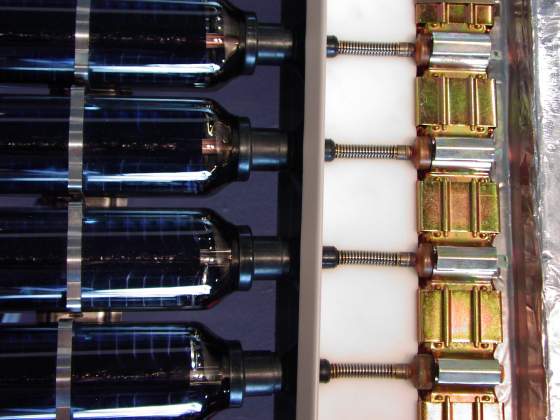
PHOTO. Connections of evacuated tubes to the solar cycle
Collector Efficiency
In order to compare collectors, test institutions usually estimate efficiency curves based on measurements of collector performance. These curves are given for different irradiances E and a variety of temperature differences between collector TC and ambient air TA. The commonly used empirical equation for the collector efficiency etaC is:
etaC = eta0-(a1·(TC-TA)+a2·(TC-TA)²)/EThe three parameters eta0, a1 and a2 are estimated by collector test measurements; eta0 is also referred to as optical efficiency. Figure 3 shows typical collector efficiencies for a flat-plate collector. The thermal losses increase as temperature difference between collector and ambient air rises. At low solar irradiances, the efficiency decreases at a faster rate; for instance, at a solar irradiance of only 200 W/m², the output of Figure 3's sample collector becomes zero even at a lower temperature difference (about 40 °C).
FIGURE 3. Collector efficiencies at different irradiances and temperature differences
Water Heating Methods
Thermosyphon systems
For storing water overnight or on cloudy days, a storage tank is needed. A very simple way of doing this, making use of gravity is shown in Figure 4 - the thermosyphon system. The principle of the thermosyphon system is that cold water has a higher specific density than warm water, and so being heavier will sink down. Therefore, the collector is always mounted below the water storage tank, so that cold water from the tank reaches the collector via a descending water pipe. If the collector heats up the water, the water rises again and reaches the tank through an ascending water pipe at the upper end of the collector. The cycle of tank–water pipe–collector ensures the water is heated up until it achieves an equilibrium temperature. The consumer can then make use of the hot water from the top of the tank, with any water used being replaced by cold water at the bottom. The collector then heats up the cold water again. Due to higher temperature differences at higher solar irradiances, warm water rises faster than it does at lower irradiances. Therefore, the circulation of water adapts itself almost perfectly to the level of solar irradiance. A thermosyphon system’s storage tank must be positioned well above the collector, otherwise the cycle can run backwards during the night and all the water will cool down. Furthermore, the cycle does not work properly at very small height differences. In regions with high solar irradiation and flatroof architecture, storage tanks are usually installed on the roof.
Thermosyphon systems operate very economically as domestic water heating systems, and the principle is simple, needing neither a pump nor a control. However, thermosyphon systems are usually not suitable for large systems, that is, those with more than 10 m2 of collector surface. Furthermore, it is difficult to place the tank above the collector in buildings with sloping roofs, and single-circuit thermosyphon systems are only suitable for frost-free regions.
FIGURE 4. A thermosyphon system
Forced-circulation systems
In contrast to thermosyphon systems, an electrical pump can be used to move water through the solar cycle of a system by forced circulation. Collector and storage tank can then be installed independently, and no height difference between tank and collector is necessary. Figure 5 shows a system using forced circulation with a conventional boiler for back-up heating.
Two temperature sensors monitor the temperatures in the solar collector and the storage tank. If the collector temperature is above the tank temperature by a certain amount, the control starts the pump, which moves the heat transfer fluid in the solar cycle; ‘switch-on’ temperature differences are normally between 5 °C and 10 °C. If the temperature difference decreases below a second threshold, the control switches off the pump again.
In regions where there is a danger of frost, a double-circuit system is usually used. Drinking water is kept inside the storage tank, while the water in the solar cycle is mixed with an antifreeze agent. A heat exchanger transfers the heat of the solar cycle to the storage tank, and keeps the drinking water separate from the antifreeze mixture.
Forced-circulation systems can be used for room heating as well as domestic
water heating. In this case, collectors and storage tanks must be much larger than with
simple domestic water heating systems, where a collector surface of about 4 m2 is
sufficient for most households. Larger systems have also been realized successfully
with two or more storage tanks.
FIGURE 5. A double-cycle system with forced circulation with a conventional boiler for back-up heating
Solar District Heating
If an entire housing estate should be fitted with solar systems, one solution is a solar district heating system (see Figure 6). The collectors are either distributed on the houses, or replaced by a large, central solar collector. The collectors then heat up a big central storage tank, from which much of the heat is distributed back to the houses. The surface-to-volume ratio of a central storage tank is much better than that for distributed storage systems, so the storage losses are much lower, and even permit seasonal heat storage. Solar district heating is also an option if room heating is to be covered by solar energy. There are higher piping losses with a central tank, but some solar district heating demonstration systems have already been successfully tested.
FIGURE 6. A solar district heating system
Solar Collector Markets
China is by far the world’s largest manufacturer and user of solar water heating. By the end of 2002, the total installed area of solar domestic hot water systems there was about 40 million m2; annual production and sales volume reached about 8 million m2 in 2002. There are now more than 1000 manufacturers producing and selling solar thermal systems, and a total turnover of more than €1 billion has been achieved. Evacuated-tube collectors dominate the Chinese domestic and export markets.
Elsewhere, about 1 million m2 of collector surface was installed in the US by 2001;
almost all of this was made up of unglazed absorbers used for swimming pool heating.
In Europe, there was about 1.1 million m2 of collector area installed by 2002, and the flatplate
collector dominates installations. About half of these installations have been realized
in Germany. The solar collector market mainly depends on political conditions in a particular
country, and in Germany, for instance, the collector market dropped by 40 % in 2002
due to uncertain political conditions, though it recovered again in 2003. However, the EU
has very ambitious targets for collector installations, with a target of 100 million m2
by 2010. Solar thermal systems will then play an important role in the struggle against
global warming.